The holiday season has now come and gone, and now that it has I can share some of the details about presents I created for Christmas. This Christmas, my family decided that many of the gifts we give should be created and not bought. I took the opportunity to practice and refine skills among my hobbies.
Specifically, I decided that I would create electronic fireflies as one of my gifts for family. I also decided that I would try to create these on their own dedicated PCBs and housings.
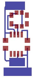
The PCBs were going to be a challenge, as I had not created PCBs before successfully, and I had chosen to use surface mount MCUs.
Before diving into the project, I leveraged an existing project to try to reduce some of the complexity I had chosen to undertake. To do this, I started with an existing asynchronous fireflies project made by Karl Lunt (Very low power LED firefly via HackADay). The overall goal is to simulate intermittent blinking in low light conditions like a firefly.
Using the existing project, I did need to modify a few things. First off, I was using an ATtiny85 instead of the ATtiny13a, as well as an external clock. Luckily, the external clock only required a few fuses to be set as far as programming went, and a couple load capacitors to allow it to be used with the MCU. The ATtiny85 required a few code changes because the output port for the LED and mux for ADC had to be changed among other registers.
Unfortunately, at this point, I did not have any through-hole ATtiny85s, so I could not breadboard the project. What else was I supposed to do at this point, besides making a PCB and hoping for the best? That’s exactly what happened. I did get a new laserjet printer during black friday last year, so I decided to try the toner transfer method. I used photo paper for the print, and Eagle to create the traces needed. I used a couple different designs for the fireflies I handed out on Christmas.

To do toner transfer, I print the PCBs mirrored on photo paper, and cut them out for transfer to the copper clad board. I’d seen a few different methods of performing the transfer, such as an iron or laminator, but I instead chosen to use a torch for heat. I sandwiched the PCB and the photo paper between two sheets of steel and heated the steel from the outside. This worked okay, achieving about a 57% success rate (4 out of 7). Luckily, I was able to get away with only handing out 4 fireflies, but I’ll digress..
After the transfer was completed, I used soapy water to remove the photo paper, and cupric chloride to etch the board. What I had read about cupric chloride suggested this would be a quick process, but it was not, perhaps because I was doing this in 30 degree weather. The process eventually produced good traces on the boards however.

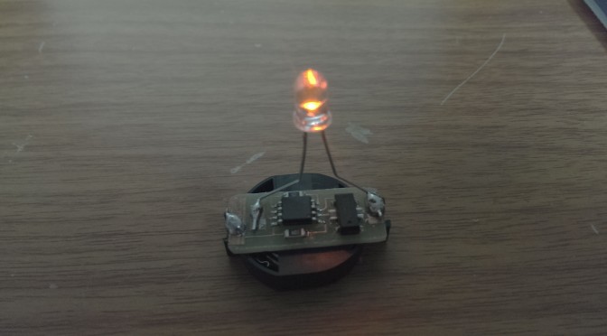
After the etching was complete, my next task was to solder on the SMD ATtiny85s. I had never done any soldering of SMD before, nor would I consider my through-hole soldering skills refined, so this was a somewhat daunting task. Anyhow, I went about this task by dabbing solder paste on the pads of the PCB and then placing the ATtiny85 on the pads. I successfully reflowed each board by using a heatgun ($9.95 harbor freight special). The heat gun works relatively well at least for this size of board, larger boards might prove troublesome. Well my reflow was mostly successful, I did get some pin bridging though, to resolve this I touched bare copper wire to the bridge while the solder was still melted; the bare copper soaked excess solder rather well (alternatively, using a soldering iron with solder wick and flux may be more reliable).
After the SMD chip soldering, the drilling and through-hole soldering needed to be done. I used a rotary tool and mini-drill bits from harbor freight to drill the board. A quick tip here: design your pads for through hole components with a hole in the center, I thought the solid pad would be just fine, but drill bits easily slide along copper when they otherwise catch the epoxy board just fine. After drilling, all the through-hole parts were soldered.
Next up was to see if I could interface with the chip and get the external clock to work. To interface with the chip, I used some tiny IC clip leads; this works well, but looks horrible. Once I had the ISP interface connected, I was able to read the device ID from the chip, and look at the current fuse settings. I made it this far, so I was pretty happy.
I, next, proceeded to change the fuse settings to use the external clock/oscillator (32kHz). Programming the fuses seemed to work well, until verification came along. The device programmer reported that the device could not enter programming mode. Noooo!!! I made it this far and now the I’ve bricked the chip (I’m aware of HVSP, but haven’t tried it yet). I tried reconnecting the chip multiple times, still couldn’t program it. I checked the interface settings, and realized I hadn’t selected an appropriate clock speed. I reduced the interface clock to 2 kHz, it’s less than one quarter of 32 kHz, so I thought I finally figured it out. Nope! Still couldn’t program the chip. I also tried swapping the crystal to see if the oscillator was the issue, no luck…
After the failed attempts to get the chip back into being able to program, I tried a last ditch effort and figured I could just use an extremely slow clock rate to program it. The GUI for Atmel Studio unfortunately only goes down to 2 kHz it seemed, so I tried this on the command line. I tried using atprogram to read the fuses with an interface clock of 1 kHz. It worked, and then I read the fuses… CKDIV8 is still set. Well, I feel silly… 2 kHz would work to program if using a 32 kHz clock, but it won’t work for a 4 kHz clock. (At this point I was confused that the Atmel GUI wouldn’t go lower than 2 kHz. That’s not the case, the slider only goes down to 2 kHz, but a lower clock can be entered in the text box, go figure…)
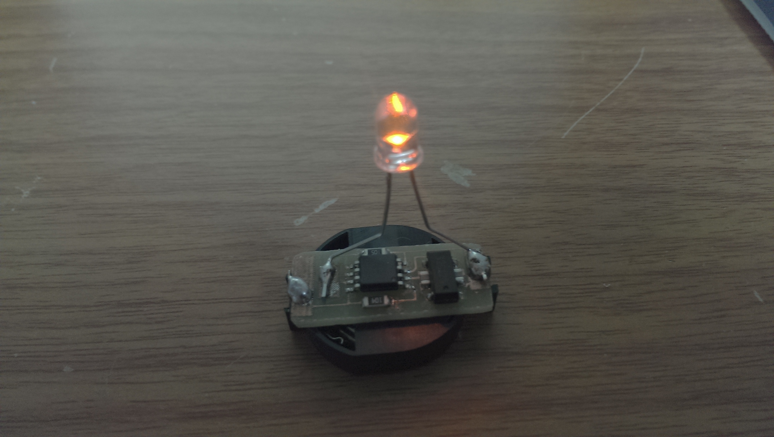
I could finally program the chip. I uploaded the modified source code to the ATtiny85, and success! A firefly was born (no crew to go with it, but eh, I’ll take what I can get…).
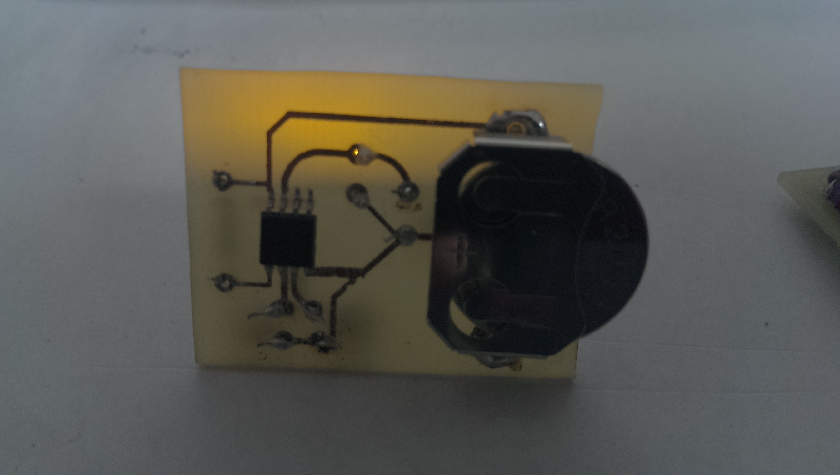
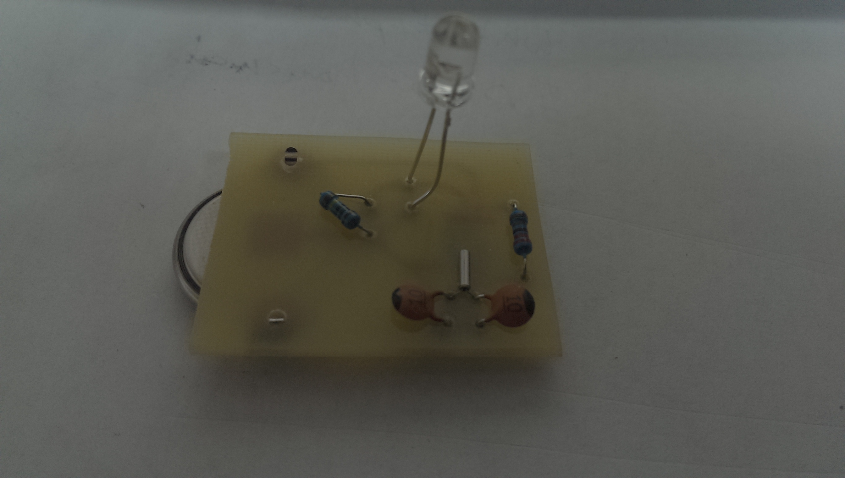

After the success of these for Christmas, I expanded my parts collection a bit, and created a full SMD version (minus battery holder and LED as it an SMD LED wouldn’t make sense). The board design and resulting firefly are below.
Part list:
- (1) ATtiny85 (ATTINY85-20SH at Digi-Key)
- (2) 12 pf 0805 capacitors
- (1) 100 kOhm 1206 resistor (for reset line)
- (1) 1 MOhm 1206 resistor (for LED discharge)
- (1) CR2032 battery holder (BC2032-E2 at Digi-Key)
- (1) CR2032 battery
- (1) Clear Orange 5mm LED (754-1271 at Digi-Key)
- (1) 32 kHz crystal (535-9166-1 at Digi-Key)
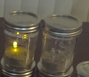
- (1) 8 to 12 oz Mason Jar
- 2-3 oz Sand
Your problem of the chip losing the verification actually gave me an idea of reviving a Arduino UNO chip that faced a similar fate a few days ago.
I will give it a try!
I do like your method to do the toner transfer method very well. Probably an idea to use two aluminium plates with the nichrome wire from an iron to make a hot press.
Making a press for toner transfer could certainly be cool. I’ve seen a number of methods that use a laminator as well, but I ultimately went with what I had.
Hopefully you can get that UNO going again!
I don’t understand why do you need a clock crystal. Using an internal oscillator + WDR clock (you can use necroleptic library) will give you ~4uA standby consumption save you using 3 external components…